
1. Introduction
The primary goal of this project is the development of a device driver
for the Connectix Colour QuickCam, a parellel port digital camera, for
the Linux operating system. While an old driver exists for the black
and white version (which is substantially different from the colour
camera), as far as I know there is no other driver for the colour
version. Most applications written for the camera under Linux use the
system call ioperm() to give I/O port access to a user level
program. This driver was intended to make the camera act like any
other unix device - so that /dev/cam could be accessed by any user
who has permission (ioperm needs to be suid root). In this way, for
instance, access to the camera can be limited to members of a certain
group, as is typical in the Unix world.
The idea of sending pictures out over a computer network is really just an
example application of the device driver - a user level server program
listens on a socket, and when it receives a request from a valid client it
opens the camera device, reads a picture, compresses it somewhat and sends
it out over the net. I originally planned to do the conversion and
compression of images actually within the kernel-level driver, but after
much consideration decided that this was not the place for it; code in the
kernel should be short, fast and to the point.
The first real problem I had was obtaining the low level Technical
Specifications for the camera: I had to sign an agreement stating that I would
not pester Connectix with questions about the Specifications and that I
wouldn't claim that my own programs are 'official' - that is, supported by
Connectix (a copy of this agreement can be found in Appendix A). Without
these specifications, however, it would have been all but impossible for me
to write the driver at all - although some work has been done on
reverse-engineering the camera, it is nowhere near as useful as the official
documentation.
2. Research
2.1 The Connectix Colour QuickCam
The Connectix Colour QuickCam is, according to its advertisements, a camera capable of transmitting pictures up to 640x480 pixels in size, in up to 24 bit colour, at a rate of up to 30 frames per second. This sounds impressive, until one checks in the list of Frequently Asked Questions at the back of the user guide (the equivalent of the small print in a contract), where the real frame rates are given. The images I will be sending, 320x240 uncompressed images and in millions of colours, are listed as 1+ frames per second. The camera will only output at any real speed using a Patented Compression Algorithm (VIDEC) which Connectix have not and do not plan to release to the public domain and third party developers such as myself. The compressed data comes out at 16 bits per pixel, and the frame-rate is about 4 times faster than uncompressed images (which are, however, better quality at 24 bits per pixel). The camera is capable of reducing the amount of data sent, at the cost of lower quality images. The pictures may be "decimated" or "zoomed" by setting the appropriate parameter (see below), which causes the camera to skip out either every second pixel and every second line, or to only send every fourth pixel and every fourth line. The 30fps claimed in the camera's sales blurb is for a 160x120 pixel compressed image with level 4 decimation, that is, skipping three out of every four pixels. This means that each picture is only 9k, as opposed to 230k full images - it's not surprising that the transfer is thirty times faster!
2.2 Technical Description of the Camera
The first part of my research depended upon finding out exactly how the camera works. The camera is made up out of an adjustable lens, a 648x496 pixel Charge Coupled Device (CCD), which registers the intensity of light, and an Infra-Red filter to compensate for the CCD's sensitivity to infra-red light. Since only intensity and not colour is caught, to form an RGB picture the data goes through a colour mask, with all colours bar one being filtered out of each physical pixel (red, green and blue) - this gives enough information to create a logical RGB 320x240 24bpp (bit per pixel - a byte each for red, green and blue, giving a maximum of 2^24 = 16,77,216 colours) image from the monochrome CCD pixels. The data is then sent, using a series of handshaking signals, via the parallel port to a computer (in this case an IBM compatible PC). The camera gets its power from the keyboard port of the PC, via a port extender, and everything is controlled by an built-in micro-controller which understands various commands sent from the PC. The camera stores images internally in a capacitive storage array, which leaks charge - it therefore automatically throws away old frames after a certain amount of time has passed (measured by an internal timer) and exposes a new frame. This constant re-exposing is internal to the camera, and happens automatically without the PC sending any commands. The camera will not send any data to the PC unless it is asked to via the correct command protocol (in the words of the authors of the technical specifications, "it only speaks when it's spoken to"). Commands from the PC are sent via a set of simple protocols. Two pins on the parallel port are used as handshaking signals, one for the PC and one for the camera. The command is then sent using the Standard Command Cycle (see Interface Specifications, page 14 - Appendix B):
- A command is written to the command bus by the PC
- The PC sets PCAck (the name of the PC handshaking pin) high
- The camera sends the first nibble (this is an echo of the high nibble of the command)
- The camera sets CamRdy1 (the name of the camera handshaking pin) high
- The PC reads the first nibble and sets PCAck low
- The camera sends the second nibble (an echo of the low nibble of the command)
- The camera sets CamRdy1 low
- The PC reads the second nibble
(For a description of the different pins and ports, see Section 2.2 "The PC Parallel Port" below). Each command is sent to the camera, which then echoes it to the PC (in 2 nibbles). This was fairly easy to implement in C - indeed a pseudo-code example was given in the Specifications (Interface Specifications, page 15 - Appendix B). The command cycle becomes slightly more complicated when a parameter needs to be read from the camera - in effect, steps 2 through 8 are repeated to receive the parameter. The way in which data is sent depends on the mode of the parallel port (for a description of the types of parallel port, see Section 2.2 "The PC Parallel Port" below). On a uni-directional port, the receiving of data looks much the same as the receiving of a parameter from the camera - steps 2 through 8 above are repeated for each byte to be received from the camera (for instance for a 320x240 frame, 76800 pixels at 24bpp means that 230400 bytes will be sent from the camera, so the cycle is repeated 230400 times), after which the camera will send an indeterminate number of 0x7E bytes followed by 0x0E, 0x00, 0x0F (ie. E0F - End Of Frame). Once this has been received, the whole cycle can begin again (the specifications recommend sending an 0x00 byte and ensuring that it is echoed correctly). On a bi-directional parallel port, the port is turned around using a special handshake between the camera and PC, and then data is read in a similar fashion, except that it is read 24 bits at a time (2 12 bit reads) and the camera handshake uses a different pin. The end of frame signal is exactly the same as in uni-directional mode, except that after receiving EOF the port must be turned around again before the starting the cycle from the beginning (again, an 0x00 byte should be sent to make sure everything is OK). The quickcam can understand a variety of commands sent from the PC. In order to set up the camera so that it will take a picture, the following commands must be sent:
- Reset
- Check version
- Set speed
- Set hue
- Set saturation
- Set contrast
- Black level
- Set exposure
- Setup frame size
Only then can a frame of video be retrieved from the camera, by sending a SendVideoFrame command and receiving the data as described above. This is all done in the function cam_init() in my code. First of all, the camera is reset by calling cam_reset(). Then the version of the camera is checked, to ensure that we are dealing with a colour quickcam. The speed is set to 2.5 Mb/s, which is the speed recommended by connectix, and the hue (hardware blue gain), saturation (anti-bloom, so that charge does not spill over from one pixel to another), contrast and black-level are all set to reasonable default values. The exposure time (aka brightness level) and white level also gets set to a default, and the frame size is set up to the maximum possible; once all this is complete the camera is ready to start sending pictures.
2.3 The PC Parallel Port
In order to actually program the camera and get it to the state where it is ready to send a picture, I had to learn about the way the camera uses the parallel port. The quickcam uses the port in a completely different way to a printer. The parallel port is a good port for general-purpose TTL logic I/O, and I spent about a week researching exactly how it works. The standard parallel port on an IBM Compatible PC is usually found at address 0x378 for the first port, and 0x278 for the second. The port is comprised of three logical ports, the Data port (at IO-BASE), the Status port (IO-BASE+1) and the Control port (IO-BASE+2). (The Quickcam Interface Specification refers to these logical ports as "Registers"). There are various types of parallel ports, but they can be broadly be separated into two categories - uni-directional (as found on older PC's), and bi-directional (SPP, ECP, EPP). Bi-directional ports function exactly the same as uni-directional ones except that when a certain pin is raised, they turn around eight of their output pins, in the Data port, so that they become inputs. Note that the camera always uses uni-directional mode (called "Nibble Mode" in the specifications) for command transfer. The Data port is a set of 8 pins that are normally used for outputting data to the printer or other device connected to the parallel port. The pins are 0v low and 5v high, and a write to this port 'attaches' the data to the pins. In uni-directional mode, a read returns the last data written to the port, however in bi-directional mode these pins are used as inputs. In uni-directional mode, this port is used by the camera exclusively for sending commands from the PC to the camera. In bi-directional mode (called "Byte Mode" in the specifications), bit one of this port is used as the handshaking signal for data transfer (CamRdy2), and the rest of the pins are used as data inputs (Data0 through Data6). The Status port has three pins which are not used (1-3), followed by four "normal" pins (4-6, 0v low and 5v high), and one inverted pin (7, 5v low and 0v high). This port is read only, and it returns the state of the five status pins. On a printer these are the signals Error, SELECT, PARAMEND, ACKIN and BUSY. The camera has different uses for them, depending on whether it is in byte mode or nibble mode. In nibble mode, bit 3 (ie the first "normal" pin) is used as the primary camera handshake signal (CamRdy1), and bits 4 through 7 are the output from the camera to the PC - this is where echoes of commands, parameters and nibble mode data are received. In byte mode, these are five input pins for data transfer (Data7 through Data 11). The camera pre-inverts command echoes and parameters which are sent through pin 7, but it does not invert image data, so this has to be done in software. The Control Port has three inverted pins (5v low and 0v high) - 0, 1 and 3. For a printer, this port is used for Strobe, Autofeed, Initialize, SELECTIN, IRQ and Bi-directional Control (pins 6 and 7 are not used). The camera uses pin 3 of this port as the main PC handshaking signal (PCAck), and pin 2 as the reset signal - raising and lowering pin 2 (Reset_N) causes the camera to perform a hardware reset. Pin 5 has the same use as for a printer - setting bit 5 high causes a bi-directional port to switch to Byte mode, so that the Data register pins become input pins as described above (on a uni-directional port, pin 5 is undefined). This port can be read from as well as written to, so that the status of the pins can be checked.
2.4 The Linux Operating System Kernel
Once I had understood how the hardware works, I had one final research task to
complete - to understand how the operating system I was writing for, Linux,
works. Although I do not have space to include a detailed description here
(because I only have a limited amount of space, and it is not strictly relevant
to the functioning of the quickcam - the parts that are relevant will be
described in section 3.1, "Coding the Driver"), this was probably the most
time-consuming and complex part of my research - and also the most enjoyable!
The Linux kernel is a very complicated program - the source code alone takes up
over 25 megabytes of information. In such a piece of software, the interface
to internal routines must be very clearly defined; these routines are defined
in Linux within the source code itself. Whenever there are any ambiguities,
one can go directly to the source and see exactly what is happening - writing
a device driver for such an operating system is therefore a comparatively
painless process, as long as one understands the code itself.
A kernel level driver has access to the entire computer, and so programming in
the kernel is a very serious business - one mistake can hang the whole system.
Kernel code has priority over user-level code, and therefore kernel level
drivers are inherently faster. This code should thus be short and fast - it
should do what it has to do and relinquish its hold on system resources. This
fact showed up an immediate flaw in my original design, where compression and
sending of images was to be done in the kernel. The kernel driver has to be
short and fast - it must take the picture, write it to user space and finish.
The camera driver has been implemented as a kernel module, rather than a
native kernel driver. This has the advantage that it can be inserted into the
running kernel when needed, and the code is not wasting valuable memory when
it is not being used. It also has the added advantage that, when compiling,
only the driver itself has to be recompiled, and not the entire kernel. A
kernel driver can be used by any user who has permission, whereas the user-space
programs that exist have to be suid root, because the ioperm() system call
only works successfully with privileged authorisations.
3. Coding the Driver
3.1 Coding a Kernel Level Driver
When I first set about actually coding the driver, my knowledge of kernel level
programming was at a bare minimum. I had an idea of the compulsory functions
and interfaces and I knew more or less how to install the compiled driver into
the running kernel as a module.
The file_operations struct, defined in /usr/src/linux/include/linux/fs.h, lists
all the operations that can be performed on a file. The device file /dev/cam
is a special file, which calls the driver in the kernel when accessed. The
device driver implements a subset of the operations listed in the
file_operations structure, and ignores the rest (if used, they are covered
by a standard implementation in the Virtual File System, which usually simply
returns an error). In this way, all of the services the cam requires,
open(struct inode *inode, struct file *file);
read(struct inode *inode, struct file *file, char *buffer, int count);
ioctl(struct inode *inode, struct file *file, u_int cmd, u_long arg);
close(struct inode *inode, struct file *file);
can be serviced by the driver, and other calls can be ignored. open() is used
to gain access to the device, ioctl() is used to set up the camera, read()
reads a picture from the camera and close() frees the camera for another
program to use.
The open() function first checks to see if the camera is already open (this is
stored in a gobal variable, in_use) - if it is, the function returns the error
-EBUSY (defined in the kernel). in_use is then set to true, and the cam_init()
function is called to initialize the camera. A static video buffer is assigned
for the pictures that will be taken, and the usage count of the module is
increased by 1 (so that it cannot be unloaded while in use). The function then
returns successfully, so that the calling program will receive a file
descriptor by which it can reference the cam in future calls.
The function read() is defined differently depending on whether we are using
a bi-directional or a uni-directional parallel port. The uni-directional
version is somewhat simple, because all of the data is read from the same
place (nibble[0-3]), but it is far slower (3:1) than the bi-directional read().
The byte mode (bi-directional) read() has to read data from the DATA port and
the STATUS port, after turning around the pins on the DATA port to accept data
from the camera. Seven bits are read from the DATA port, and five from the
STATUS port, making a complete twelve bit read (two of these reads make up
one pixel, while two reads in nibble mode make up one byte, which is one third
of a pixel). The data is then copied to the supplied user-space buffer using
memcpy_tofs(), and the function returns the number of bytes copied (this should
always equal 230400).
I use ioctl() in the camera to pass a quickcam struct from user-space - this is
possible because the parameter arg is an unsigned int, and sizeof(u_long) is
equal to sizeof(void*), so I am really passing a pointer to user-space cast
to an unsigned long. The driver's internal camera struct is updated to the
values in the new struct, so by using ioctl() a program can set the camera
parameters to whatever values it likes within the range allowed.
Finally, the close() function is probably the simplest function - it releases
the video buffer that has been allocated, resets the camera, sets in_use to
false and decreases the module use count, so that the module can be unloaded.
There is one other function from the file_operations struct that is overrided
in the code,
write(struct inode *inode, struct file *file, const char *buffer, int count);
This function is overridden simply for completeness, so that if someone does
try to write to the camera they will be told that they cannot before the
function exits.
Apart from the functions listed in the file_operations struct, the driver has
to implement two functions which are necessary for any kernel module, namely
init_module() and cleanup_module(). init_module() first makes sure that the
address of the hardware is not in use by another driver, such as lp.c (the
standard printer driver), by calling check_region(). If the address is
currently reserved by another driver, the module will give an error message
and refuse to load. If the address is free, init_module() will try to reserve
it using request_region(), and register the driver in the kernel by using
register_chrdev(). All of these functions are part of the kernel's pre-defined
driver interface. Finally init_module() allocates some default values for
the internal quickcam struct, and initialises the cam by calling cam_init().
cleanup_module() simply reverses what init_module() has done - it calls
release_region() to free the hardware address for other drivers, and
unregister_chrdev().
3.2 Hardware Limitations
At first, my work was limited by the hardware I had available. The computer I started work on was an old 386DX/40 with 8 megabytes of RAM, a 128k cache and a 120Mb hard disk, which I had put together from some old scraps, but worst of all was the fact that it only had a uni-directional parallel port, so I was limited to Nibble mode data transfers, which are three times slower than the transfer rate on a bi-directional port. I spent this time learning about kernel level programming, mainly by reading and tracing through the kernel code, and writing a module that works only in Nibble mode. The code went through revision after revision, changing a number of times - the CHANGES document distributed with the code (see Appendix) describes exactly what changed from version to version. After revising and rewriting the module six times, I finally bought a new parallel port card which had a bi-directional parallel port. This obviously increased threefold the speed at which the driver could output images, and involved a complete rewrite of the cam_read() function. I decided to make the type of parallel port a compile-time decision, mainly because it's not often that people change their parallel ports, and the amount of code in the kernel should be kept to a minimum.
3.3 Optimisation
Once the working kernel level driver was written, I moved on to try and
optimize it for speed. The hardware I was working on was very slow, and every
possible increase made a difference.
One example of optimisation was moving the definitions of the DATA, STATUS and
CONTROL ports from the internal kernel camera structure to #defines in the
makefile. While this may not seem important, I obtained a speed increase of
around 40% on my old 386DX40, after looking at the assembler output of the
code. Each time any function wanted to access any of the ports, it had to load
the camera struct into a local variable and access it as an offset from the
beginning of the struct. Compare for instance this excerpt from the
ReadParameter() function:
ReadParameter: ReadParameter:
pushl %ebp pushl %esi
movl %esp,%ebp pushl %ebx
subl $4,esp movb $6,al
pushl %edi movb $890,edx
pushl %esi outb %al,%dx
pushl %ebx
movl cam,%eax
movl 4(%eax),%eax
movl %eax,-4(%ebp)
movw -4(%ebp),%cx
addw $2,%cx
movb $6,al
movl %ecx,%edx
outb %al,%dx
After the tenth code revision, I finally decided that the camera driver was
stable enough to be used as a basis for writing the client-server applications,
and so I stopped work on the driver (although see section 6.3, "Future Plans",
for what I would have done if I had the time).
3.4 Demonstration Programs
Before starting the client-server applications, I decided it would be useful to
have a set of working programs that would demonstrate that the driver indeed
works effectively. These programs were developed along with the driver itself,
but after I made a conscious decision to stop developing the driver further, I
kept up work on the applications to try and produce some software that may be of
some use for someone.
There are three example applications which I wrote: photo, vidcam and takepic.
photo is perhaps the simplest of them - all it does is display a picture on the
screen when a key is pressed, and optionally save it to a file. The idea was to
create the effect of a camera, where you can preview your photos and then
keep them if they look alright. Photo simply writes a ppm file to disk, which
is basically a raw write of RGB values (see section 4.3, "Image Formats").
vidcam is a more advanced version program, which makes the quickcam act as a
primitive form of video-camera. It can zoom in and out, using the decimation
facilities provided by the quickcam, and it can move around the picture when
zoomed in, choosing the appropriate section of the CCD and displaying it on the
screen.
photo and vidcam both utilize the svgalib library for displaying images on the
screen. This means, unfortunately, that they must be suid root to run (thus
nullifying one of my main reasons for writing a kernel level driver accessible
by all), but I simply did not have time to write my own routines - I did
consider writing a pseudo /dev/vga device which gives the required permissions
when opened, and making it readable by a certain group, say vga, and then
directly programming the vga hardware (which is not a difficult task), however
as these programs are not strictly speaking part of what I planned for my
project I decided that the development time was not worth the gain. (The idea
of a pseudo /dev/vga device is given in the documentation for svgalib as a
possible alternative to suid root).
takepic is without doubt the most useful of the three applications. Although
it started as a demonstration program, it became a part of the final
client-server mechanism (the server calls takepic to access the driver).
takepic takes as its arguments the number of pictures to take, an optional
amount of time in seconds to wait between each frame, and a prefix to the
name of the picture. It takes pictures from the camera, and saves them as
jpeg files using libjpeg (see section 4.3, "Image Formats"). The files are
numbered, using the prefix supplied, in the form prefix1.jpg, prefix2.jpg etc.,
and written to the current directory. One of the many possible uses for this
program is to create videos - using mpeg_encode (a freeware mpeg movie format
encoding program), a large number of images can be turned into a video stream.
I have personally used this combination to make a classic video of a rose
blooming and withering - by leaving takepic running in the background, to take
a picture every five minutes for two days, giving 376 images which I then
encoded into an mpeg video stream - or, for instance, a video of a sky full of
clouds, rushing along at high speed: the possibilities are really only limited
by ones imagination.
4. Research - Client/Server
4.1 Socket Programming
My original idea was to have images sent directly from the camera, still in kernel space, to the ethernet driver and from there out onto the network. However, as mentioned above, I soon discovered that kernel code has to be short and swift, and compressing images, wrapping them up in TCP/IP headers and sending them over the network is not a task for the kernel. I therefore had to learn about the interface to network programming, using AF_INET sockets. Sockets are the standard way of sending data over an IP network, and using TCP sockets for a two way connection is a standard part of most modern programming languages. I had to choose a high level language that I knew, that was easy to program in and could support sockets. I first chose C, because it is the language I probably know best, and it has very good support for sockets - a socket is treated in the same way as a file or a device, using open(), read(), write(), close(), and some extra functions particular to network connections, such as connect(), bind(), listen(). My first working socket client/server programs in C are listed in Appendix, although I later changed to another language (see section 5.4.2, "Why Perl?").
4.2 Network Transfer Speed
The biggest problem with transferring anything over a network is transfer speed. The most common ways that people connect to the internet are via modems and ethernet, the former usually used privately by single people, the latter most often by organisations connecting their own local lans. A slightly faster way of connecting private individuals is via ISDN adaptors, which are becoming increasingly more popular. Modern modems nowadays are capable of receiving data at 57.6kbit/s, and sending at 33.6kbit/s. ISDN adaptors using one B channel of an ISDN connection can send and receive at 64kbit/s. Ethernet cards are usually designed to work at 10Mbit/s, although newer cards can transmit and receive at up to 100Mbit/s, and ATM networks can be far faster. In order to transfer a 230k picture in one second, the minimum connection speed must be around 2Mbit/s, which is the bandwidth of a standard PCM (ie. 32 channel B ISDN connections working in parallel with some kind of load equalizing would be needed to work at this speed). This is not realistic, so if I wanted to achieve any reasonable kind of speed for dial-up users at home, I had to find some way to radically compress the data. 64kbit/s gives a maximum transfer speed of 8192 bytes per second, so for one second picture transfers over ISDN, I had to compress a 230k picture into 8k of data!
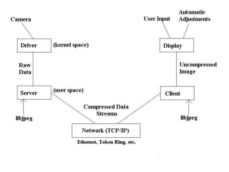
4.3 Image Formats
The quickcam sends data in a raw RGB image format - one byte for each of red,
green and blue in each pixel, giving a possible 16 million or so colours. This
format is most easily converted to the ppm standard, which stores its data in
exactly the same way, adding a simple header which states the height, width and
number of possible different values for each colour (eg 255, which is the full
one byte for each of red, green and blue). However, this format creates files
which are 230400 or more bytes long and, as described above, this is far too
large to send over a network.
There are many kinds of image format: gif, tiff, pcx, bmp, tga and png to name
but a few. I tried a number of formats before 'discovering' jpeg, a format
which is very common on the internet mainly because of its small size and its
ability to store real-world photographs in good quality. The Independant JPEG
Group's libjpeg is a set of routines in c for encoding and decoding jpeg format
pictures. Using their well defined yet simple interface, it is easy to convert
a picture to jpeg format. The rate of compression is astounding - an average
file size of 8kb holds the same picture as the 230k ppm file! Above all, the
jpeg compression using libjpeg is fast, far faster than conversion to any of
the other formats which I tested.
Jpeg is designed to handle "real-world" scenes such as scanned photographs, or
for instance pictures taken by digital cameras. Jpeg is what is known as a
'lossy' compression format, meaning that it does not necessarily reproduce
exactly the same picture as its input, but a very near approximation. In
practice, this difference, for my purposes, is completely irrelevant - I do not
need the pictures to be exactly the same pixel for pixel, but simply to look
the same (the difference between the input and output image is a matter for
concern only in programs where the images have to be the same byte for byte;
in such programs, a 'lossless' format must be used). There is in effect no
visible change for real-world scenes.
takepic takes a picture from the camera as raw digital data, then uses libjpeg
to compress it and write it to a file. This became part of the final
client-server mechanism, mainly because the C libjpeg routines are the fastest
that I could find!
5. Coding the Client/Server Applications
5.1 My Client/Server model
The final model on which I based my client/server applications was as follows:
Firstly, the client opens a socket connection to the server, and sends a HELO. The server answers CAM, and then waits for SEND requests from the client. The client sends a SEND to the server, waits for a DONE reply, and then gets the picture via a URL (the reasons for this are listed in section 5.5, "Displaying pictures in Java", below).
5.2 The Server
I chose perl for the server because it is a very simple language to program in, and has very good support for BSD compatible sockets, via its Socket module. The server is based on the perl manual pages and example code, and in truth is very simple. It is a 'multi-threaded' server, meaning that it can handle a number of connections at once (although this still needs work from the client side - at the moment if there is more than one connection active from the same host, the image becomes corrupted because one client accesses the picture when the server is re-writing it for the other client - see section 6.3, "Future Improvements"). The actual interface to the camera is done by calling takepic, which is actually written in c. This is not because perl is incapable of taking the picture (perl can do practically anything that C can do), but because the C libjpeg routines are far faster than any of the possible solutions in perl. Perl is a two phase interpreted language (on the first pass, syntax etc. is checked, and on the second the program is actually interpreted), which actually makes it slightly slower than a compiled language such as C (although there are perl compilers in development). The main reason for using perl instead of C for the final server was the superb string-handling facilities that perl offers, far more logical than (and indeed superior to) those available in C. Although this may not seem completely relevant to the client-server mechanism as it stands, see section 6.3, "Future Plans", to understand the kind of strings the server is supposed to be able to handle. Perl (which stands for Practical Extraction and Report Language) was designed for handling and manipulating text, and I believe in using the most adequate tool for whatever I am doing.
5.3 The Client
What made java the best choice for my client was the fact that a java applet
(indeed, in theory, any java application) once written will run on any machine
that has what is known as a Java Virtual Machine (JVM). Java Virtual Machines
are part of most modern web browsers nowadays, so my applet should run just as
well on a Sun Sparc Server 20 running the Navigator 4.0 web-browser from
Netscape Communicator, as it will on an intel x86 compatible running windows NT
and Microsoft's newest Internet Explorer. This means that one computer running
linux and the camera driver and server software can serve as a camera server for
and entire network of different kinds of machines - anyone, from any kind of
computer, can see the pictures.
Java is a completely object oriented language, and as such everything in a java
program is an object. The socket object, which I use to connect with the camera
server, is and object with various methods and constructors, most of which do
exactly the same as the socket calls in other languages. The constructor which
I found most useful takes as its parameters an internet address (also an object)
and a port number, and opens a socket connection to that address. The actual
socket has the system default type of SocketImpl, which is the abstract class
that prototypes all the methods used in socket communication (ie. accept(),
bind(), close(), connect(), listen() etc.).
Java also has a fairly simple yet efficient string-handling mechanism. Since
everything is an object, the object String has its own constructors and methods
such as charAt(), compareTo(), concat(), endsWith(), indexOf(), length(),
regionMatches(), replace(), startsWith(), substring(), trim(), etc. etc., all of
which make java string handling easy to use and understand.
It may seem at first glance that there is very little difference between a java
applet and a java application; however, this is not the case. They are vastly
different, and this is mainly due to the major limitations of applets.
The rationale behind applet "security" is to make applets safe to use. Thus
they do not have access to the local computer that they run on; they cannot
make network connections to any computer other than the one they came from;
they are limited to doing only what the Java Virtual Machine they are running
on can actually do, and so on. Although this does indeed make applets "safer"
to use than for instance Microsoft's ActiveX (which can access anything on a
system using one of Microsoft's operating systems, and therefore is succeptible
to abuse by virus-writers and crackers), it makes programming Java applets very
different to programming Java applications.
Java is a language designed for multimedia, and it is a very useful tool for
displaying animated images in web-pages. Images are stored in an Image object,
because everything in java is an object, and there are various ways of getting
image data into an Image object. However, in order to take advantage of java's
built-in decompression of jpeg images, the image has to be downloaded via a
URL object. Java then automatically sets up the colour model, imageProducer,
decompression and so on, and creates an Image object (if I was to download the
data directly via a socket, I would have to do all of this myself, and I did
not have time to prepare something like this within the scope of this project -
see section 6.3, "Future Improvements").
6. Conclusion
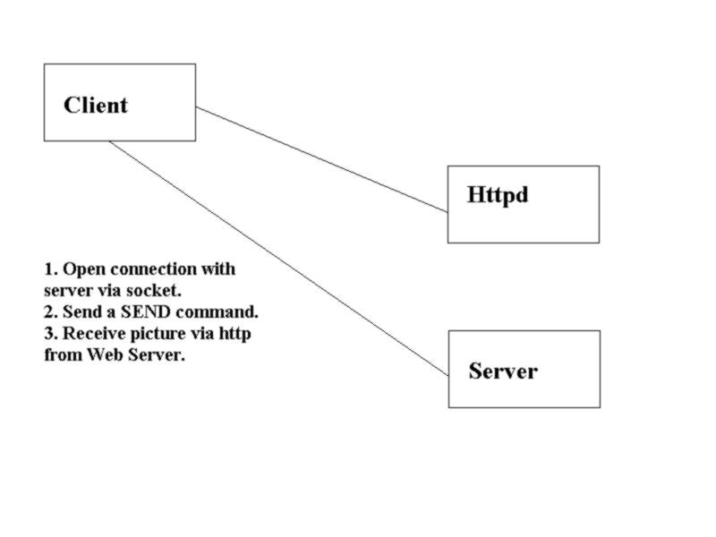
There are a number of things that I would change, given more time (and indeed I hope to find the time and resources to keep developing this software even after submitting this project). The high-level design of the client-server protocol would be completely different, and would implement a real protocol which I started developing but did not have time to complete. The final set of client-server programs would be fully capable of handling many connections at once, and sending the same pictures to each connection. Above all, however, the picture would be passed through the socket connection from the server, decoded manually in the client and displayed bit-blitted on the screen - the current implementation is rather ugly. My final design for a client-server program would look something like this:
It relies on a simple protocol I developed, called QCP/JIP (Quickcam Control
Protocol/Jpeg Transmission Protocol), which is supposed to function in the
following manner:
Client Server
(opens connection) ++ CAM SERVER Vx.xx READY
SEND ++ OK PICTURE SIZE xxxxx
(or, if command invalid) ++ ERR INVALID COMMAND
SIZE xxxxx OK ++ DATA
(or, if SEND not sent yet) ++ ERR SIZE BEFORE SEND
(data is transferred here)
++ ENDDATA
OK RECEIVED xxxxx BYTES ++ CAM SERVER Vx.xx READY
(or, if SIZE not sent yet) ++ OK BEFORE SIZE
To set parameters, the client would use:
Client Server
PARAM xxxxx xxx ++ OK PARAM xxxxx NOW xxx
(or, if xxxxx is invalid) ++ ERR INVALID PARAM xxxxx
(or, if xxx is invalid) ++ ERR INVALID VALUE xxx
(or, if command invalid) ++ ERR INVALID COMMAND
Various security levels can also easily be added, for instance:
A client has to log in with a valid password in order to access the camera.
Open access to pictures, but a password is required to change parameters.
A password for some parameters (eg. contrast) but not for others (eg. zoom).
This high level design is what I started working towards, but unfortunately
time began to run short, and I had to alter it rather drastically (practically
no protocol, images being read via a URL object in order to call java's inbuilt
JPEGImageDecoder object instead of manually decoding and displaying bit-blit,
etc. etc.). The handling of more than one connection could also be much
improved - at the moment, if there is more than one connection, the speed of
each is slowed down by the other, and if there are two connections from the same
host they distort each-other's pictures. This could probably be done by
synchronising the children spawned by the server software so that they all draw
on the same image, but this would only be possible once the image is sent
directly via the socket connection, and not via a seperate URL.
It would also have been interesting to have experimented with more advanced
image compression techniques. Although 230k - 8k is extremely impressive (even
for jpeg), had time allowed I would have liked to implement the idea of a kind
of abbrieviated jpeg datastream. A normal jpeg file contains several hundred
bytes worth of quantization and Huffman tables; these can be omitted when
sending a number of images where the tables are identical, saving this overhead
from being repeated image after image after image. How far this would be
possible in this situation is something I did not have time to explore, and it
is not often done in a networked situation, because of the existance of mpeg
video streams - this is also something I would like to explore.
The facility provided by libjpeg for source and destination managers would also
have provided a great improvement in the client, both in speed and general
logical structure. By embedding the C libjpeg routines directly in the perl
server, I could make the source manager take its input directly from a read()
of the camera, and the destination manager send the compressed data directly to
a socket. This would be far tidier than the current implementation, and of
course far faster than calling an external C program to access the camera,
compress the image and write the data to a file.